1. Definition and Structure of Shell-and-Tube Heat Exchangers
Shell-and-tube heat exchangers, also known as shell-and-tube exchangers, are extensively used in industrial heat exchange applications. Comprising a shell, tube bundles, tube sheets, baffles, and tube boxes, these exchangers house tubes within a cylindrical shell, with both ends of the tubes fixed to the tube sheets. The hot and cold fluids involved in heat exchange flow inside the tubes (tube-side fluid) and outside the tubes (shell-side fluid), respectively.
2. Working Principle
The heat transfer in shell-and-tube heat exchangers occurs through the walls of the tubes within the cylindrical shell to the colder fluid. To enhance the heat transfer coefficient of the fluid outside the tubes, baffles are installed inside the shell. These baffles increase the velocity of the shell-side fluid, causing it to pass through the tube bundle multiple times along a specified path, thereby enhancing fluid turbulence.
3. Types and Characteristics
- Fixed Tube Sheet Exchanger: Features a simple and compact structure, is cost-effective, and widely applied. However, it cannot be mechanically cleaned on the outside of the tubes.
- Floating Head Exchanger: The tube sheet at one end can move freely to accommodate thermal expansion, referred to as the "floating head," making it suitable for applications with significant temperature differences where the tube bundle requires regular cleaning. The structure is more complex, leading to higher manufacturing costs.
- U-Tube Exchanger: With a single tube sheet, the tubes can expand and contract freely upon heating or cooling. This simple structure is limited by the need for a certain bending radius of the tubes, resulting in a lower utilization rate of the tube sheet and difficulty in mechanically cleaning the inside of the tubes.
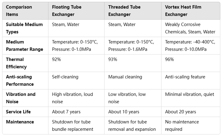
- Vortex Heat Film Exchanger: Utilizes vortex heat film heat transfer technology to improve heat exchange efficiency and offers corrosion resistance, high-temperature resistance, high-pressure resistance, and anti-scaling capabilities.
4. Performance Comparison Table

5. Selection of Design Parameters
The design of shell-and-tube heat exchangers involves considering parameters such as the tube box, shell, tube bundle, baffles, and anti-impact plates. These parameters determine the type, specifications, and performance characteristics of the heat exchanger. For example, the selection of the front tube box primarily considers maintenance needs, the hazards of mixing fluids in the tube and shell sides, and the pressure in the tube side.
6. Manufacturing Process
The manufacturing process of shell-and-tube heat exchangers is relatively simple, with low production costs and a broad range of material options. The heat exchange surface is easy to clean, offering strong adaptability and processing capacity. In the manufacturing process, the fabrication of the cylinder, head, etc., is similar to general container manufacturing, with different requirements, focusing on material inspection, drilling of tube sheets and baffles, cylinder welding, and flange processing.
7. Application Fields
Shell-and-tube heat exchangers are widely used in various fields such as petroleum, natural gas, petrochemicals, food processing, pharmaceuticals, special chemical processes, HVAC, district heating, energy, and others.
The above content provides a comprehensive discussion on shell-and-tube heat exchangers, including definitions, structure, working principles, types, performance comparisons, design parameter selection, manufacturing processes, and application fields. It is hoped that this information will be helpful for your research or engineering applications.
